1. INTRODUCTION
In order to perform its unique mission, a satellite must be oriented in the required direction in its mission orbit. In other words, when an earth observation camera is mounted, the camera must be oriented toward the earth in order to perform the observation mission. In addition, when a payload carrying out a space science mission is loaded, the attitude of the observation device must be controlled so that the sensor is aimed toward the direction of space. At this time, there can be various types of actuators required for attitude control of a satellite. Currently, the reaction wheel is the most widely used driving device for high-precision attitude control of satellites. The reaction wheel is most commonly used as an attitude-control drive device for ultra-small cube satellites, small-scale satellites, and mid- to large-scale satellites, as considerable amounts of heritage and reliability in space must be guaranteed. However, the torque generated by reaction wheels is extremely limited. In other words, only relatively low torque is generated, making this device not feasible for use when it is necessary to control the direction of a satellite quickly. In particular, it has the disadvantage of not being able to generate the fast rotation speed of 1 to 10 deg/s required by earth observation satellites or military satellites that require high mobility [1]. In general, this level of required fast maneuvering is a performance metric that cannot be met by a momentum exchange actuator (momentum wheel assembly, MWA) or a reaction wheel (reaction wheel assembly, RWA) of the types currently mainly used in satellites [1]. A control moment gyro (CMG) is typically used as an actuator to meet these performance requirements [2–4]. The development of technology for the CMG, which generates the large amounts of torque required for high mobility and attitude control, is ongoing. Among actuators that use the momentum exchange principle, the CMG can produce high torque and has therefore been commonly used in two types of satellites that require such high torque levels in the United States since the early 1970s. One has been used in satellites with a very large moment of inertia, such as a space station, and the other finds use in the rapid maneuvering of earth observation military satellites, which require agile maneuverability [5]. Missions requiring agile maneuverability are steadily increasing and include military satellites, observation satellites, and satellite-based scientific missions. Therefore, the development of a CMG suitable for micro-satellites began in 2022 through cooperation between domestic industries, academia and research institutes. In the present study, we introduce the development status of the hardware, software, and mounting methods used in the development of ultra-small CMGs that can be mounted on domestic satellites.
2. CMG SPECIFICATIONS
Satellites can be classified into various types according to factors such as their weight and mission. In this study, development standards were established while taking into account the physical characteristics of the ever-increasing number of microsatellites. In relation to this, satellites have various moments of inertia (MoI) depending on their mission-based configuration. Table 1 below describes the pros and cons of rapid maneuvering when using the RWA or CMG strategies depending on the development shape of the satellite structure.
MoIs of various sizes are calculated according to the various shapes of microsatellites, and CMG development specifications suitable for microsatellites capable of rapid maneuvering on each axis have been defined and developed, as shown in Table 2.
| Items | Specifications |
|---|---|
| Momentum | 800 mNms |
| Torque | 800 mNm |
| Dimensions | 106 mm × 106 mm × 158 mm |
| Mass | 3.5 kg |
| Communications | RS422 |
| Voltage | +28 V |
Table 2 shows the possible satellite configurations, and the MoI for each configuration has different values. Assuming CMGs are mounted on a small satellite, MoI depending on the satellite configuration is distributed from 1.5 kgm2 to 60 kgm2. Therefore, this CMG determined the CMG’s specifications that can maneuver at 10 deg per second considering the configuration of the small satellite as shown in Table 1.
3. CMG DESIGN
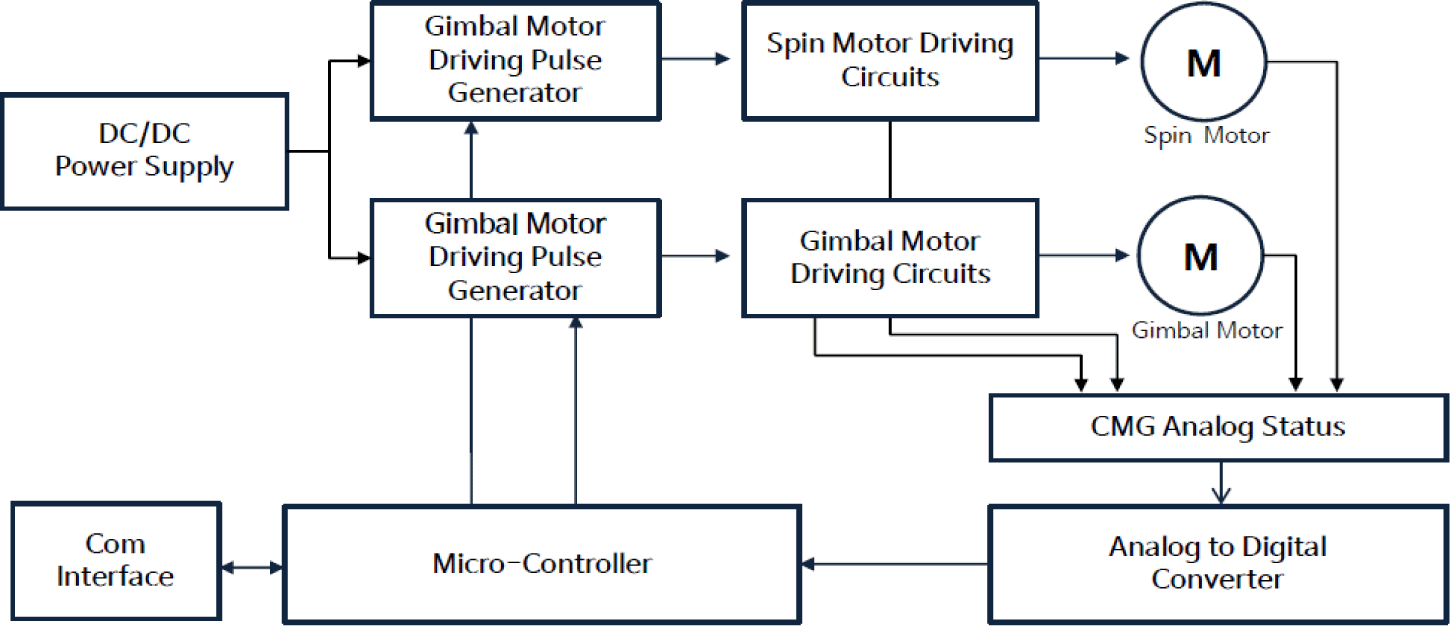
A CMG consists of a spin motor that rotates at a high speed and a gimbal motor that generates high torque by controlling the angular speed of the spin motor as it rotates at a high speed. Because it must be used as a highly agile attitude-control driving device for ultra-small satellites, all circuit parts that can be commonly applied are unified in consideration of the volume and power consumption (Fig. 1).
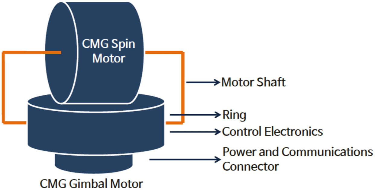
Spin motors rotate at high speeds and thus there should be no interference with surrounding structures or electronic components. Therefore, the shaft is configured as shown in Fig. 2 below for stable support when the spin motor rotates at a high speed. In addition, in order to generate high torque from a spin motor rotating at a high speed, the structural shape is designed to enable control of the gimbal motor at a constant angular speed. Data and power between the two motors are supplied through a slip ring. The rotational angular speed and status information of each motor are obtained through the slip ring and a communication transceiver at the bottom.
The torque direction of each CMG must be controlled to generate a high torque in a specific direction so that the target can be quickly maneuvered using the rotational angular velocity of the spin motor rotating at a high speed. In general, driving force is obtained by using a RWA and CMG in a cluster format to generate the torque necessary for posture maneuvering. For missions that do not require agile maneuverability, the RWA is configured in a certain format to ensure the necessary attitude-control driving force. Satellite three-axis attitude control using a RWA involves a pyramid shape. Each RWA remains in an uncontrolled state when the rotation speed is saturated above a certain speed. Fortunately, for the RWA, the saturated rotational angular velocity can normally be controlled using a magnetorquer. For the CMG, there are certain gimbal angle sets where certain directions of torque cannot be generated. Maneuvering performance is degraded in such gimbal angle sets; target torque could not be generated as intended, falling into uncontrollable states. Such uncontrollable case at the specific gimbal angle state is called a singularity, and an algorithm must be implemented to avoid such an area when the CMG operates. Fig. 3 below describes the pros and cons of each cluster configuration. The pyramid-type arrangement has an advantage such that the available momentum envelope is not biased in a specific direction. Therefore, the momentum capacity can be distributed evenly, and this arrangement is ideal for three-axis posture control [6]. However, because there is a complex area in which singularities exist within the momentum envelope, there is a high possibility that maneuvering will be disrupted at that point [7]. In addition, there are cases in which singularity avoidance inevitably involves a change in the angular momentum, which has the disadvantage of making the mounting and use of this arrangement difficult on an actual satellite [6].
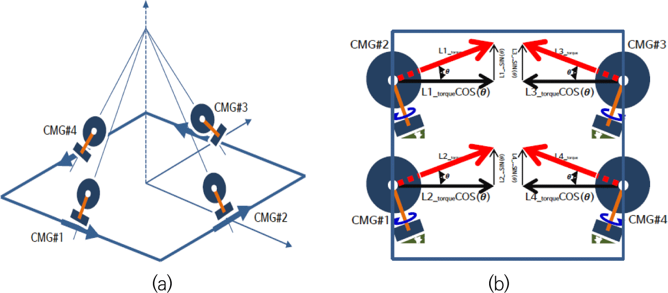
The rooftop-type arrangement is a CMG arrangement that has been widely used recently. Unlike the pyramid-type arrangement, the area in which the singularity exists inside the momentum envelope is simple, offering the advantage of relatively easy singularity-avoidance maneuvers [8].
For a rooftop CMG array, if six or more wheels are used, attitude-control maneuvers can be performed without restrictions due to singularity problems. Additionally, even when only four wheels are used, the singularity problem can easily be solved through feasible methods such as limiting the operation area of the CMG gimbal or applying null motion [9]. However, because the momentum envelope is elongated in a specific direction, there is a disadvantage in that the momentum capacity is not evenly distributed. However, this feature is not always necessarily a disadvantage because the momentum capacity can be increased on a specific axis when high-speed maneuvering is required [6].
4. CMG MANUFACTURING AND TEST RESULTS
The main hardware components make up the CMG are magnets, coils, and bearings. The CMG, a driving device applied to a satellite, is a component that rotates continuously after launch and continues to operate until the end of the mission. Therefore, it must be manufactured with parts that are highly reliable at the manufacturing stage. In addition to the electromagnet component, a spin motor and a gimbal motor are used as driving parts, with these motors controlled by the satellite using a field effect transistor (FET). Among CMG components, slip ring parts are used to ensure the electrical connection between the spin motor and the gimbal motor.
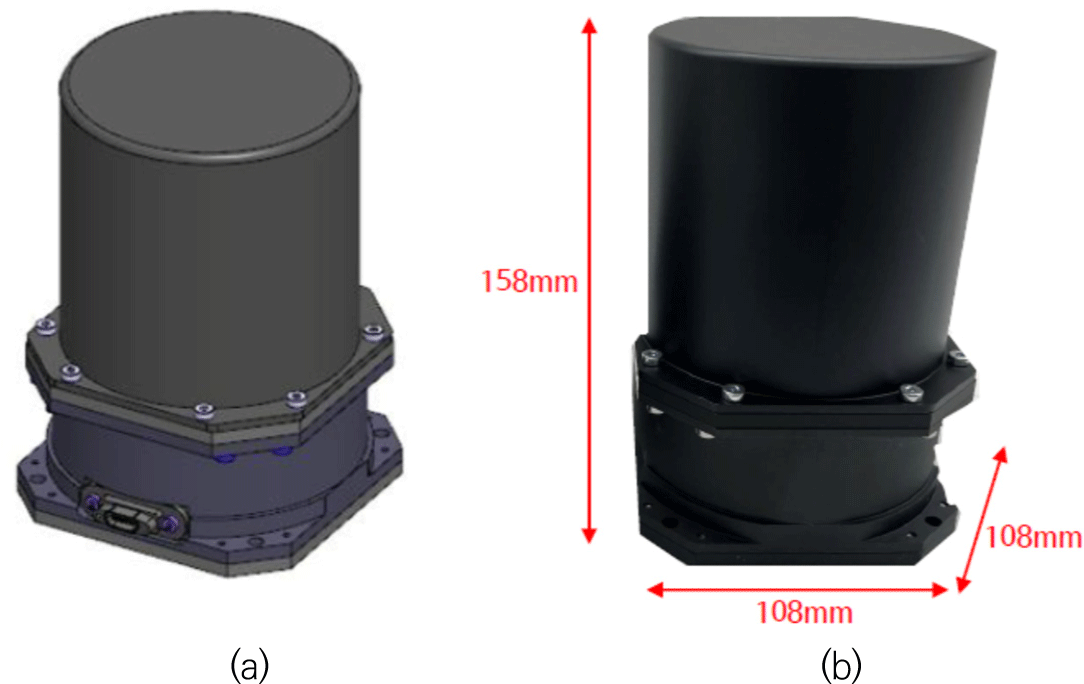
The design of the bottom of the CMG included bolt holes for assembly onto the satellite. The CMG internal spin motor rotates at a high speed and is manufactured with simulations of the bolt quantity and diameter to minimize the effects of vibration. Fig. 4 shows the internal shape of the 800 mNm CMG and the shape in which the cover is manufactured. The overall size considering the CMG cover, at 108 mm × 108 mm × 158 mm, was selected with the goal of mounting a micro-satellite.
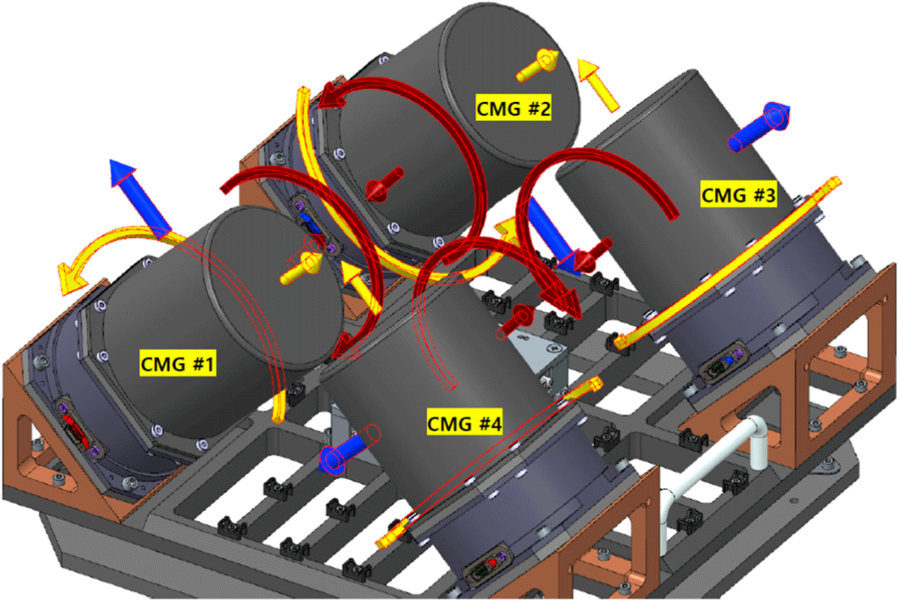
The CMG cluster consists of a total of four clusters. CMG #1 and CMG #2 were manufactured to be arranged on the same axis, and CMG #3 and CMG #4 were also arranged on the same axis. Additionally, an electronic control device for data distribution and for the power supply was placed in the central part of the CMG cluster.
In the CMG cluster configuration, the spin motor rotates in the direction of the red arrow. The CMG gimbal motor rotates in the direction of the black arrow in Fig. 5, and the torque of an individual CMG is shown in blue in Fig. 5. When these torque values are added in the vector direction, torque and momentum suitable for high mobility are generated.
The pros and cons of the CMG combination were described in previous research results. Therefore, an operability test according to the CMG cluster production was conducted, as shown in Fig. 6. The main components tested here consisted of a CMG cluster, a power supply, and control software. The CMG cluster and control computer were configured to be connected via a USB communication link.
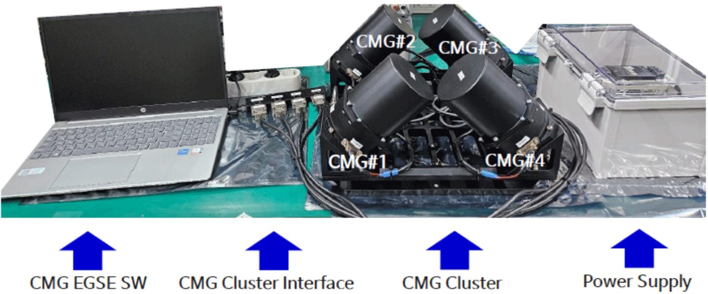
The basic operation and torque generation of the CMG were tested in the environment shown in Fig. 6, and the results shown in Table 3 below were derived.
| CMG# | Requirements | Spin motor speed | Gimbal motor speed | |
|---|---|---|---|---|
| Spin speed | Gimbal speed | |||
| 1 | 0–5,000 rpm | 0–2 arcsec/s |

|

|
| 2 | 0–5,000 rpm | 0–2 arcsec/s | ||
| 3 | 0–5,000 rpm | 0–2 arcsec/s | ||
| 4 | 0–5,000 rpm | 0–2 arcsec/s | ||
5. CONCLUSION
Satellite attitude-control technology using reaction wheels is a very old technology, continuing to find use, however, as it is a highly reliable technology. However, the torque value is low and insufficient for satellites that require quick control of the attitude and that must observe a target during flight. The reaction wheel has a rotational angular speed of about 1 deg/s per second, making quick rotations virtually impossible. Typical missions are complex and rapid attitude control of the satellite is necessary to observe various targets in a limited time. Hence, a CMG must be used to meet the rotational angular velocity per second requirement of at least 10 deg/s. Here, a CMG study was conducted to generate torque suitable for microsatellites. Although various types of satellite shapes have been designed, a CMG development standard was established considering the MoI value according to the shape of an earth observation satellite. The torque generated by the developed CMG is approximately 800 mNm, and tests were conducted of its functional operating capabilities by forming a cluster. It was confirmed through testing that each CMG generates torque of 800 mNm. In order to be mounted on a satellite, a CMG cluster configuration was used, and it was confirmed through production that each CMG meets the performance of a CMG suitable for a micro-satellite considering the corresponding vector value.


