1. INTRODUCTION
Advances in semiconductor technology have accelerated the development of satellite technologies. Even just 20 years ago, performance outcomes such as the resolution compared to the size of a satellite were not efficient. In other words, the resolution of an earth observation satellite could be increased by increasing the size of the optical system aperture. However, with recent advances in electrical and electronic technologies, hardware and software technologies have been developed such that it is now possible to increase the resolution while reducing the size of the optical system aperture. With regard to the scale of satellites, their size and volume have become significantly smaller. However, despite the improvements in performance capabilities, there has not been much change in terms of usability. As one example, it is important for Earth observation satellites to secure a large amount of imagery but to maintain a small quantity. Earth observation satellites are now required to have more rapid rotational maneuverability and other abilities than compared to those in the past. These satellites, known as agile satellites, require attitude control systems that can provide rapid multi-targeting pointing and tracking capabilities. An agile satellite is much more efficient and functional, and data return of substantially increased by given agility [1]. In particular, when considering uses such as surveillance and reconnaissance, securing video in real time is paramount. Currently, images using optical cameras mounted on Earth observation satellites capture target points after an appropriate attitude control step. Attitude control of Earth observation satellites uses a reaction wheel assembly (RWA). The existing RWA is an essential driving device for attitude control of satellites. From ultra-small cube satellites to very large geostationary satellites, the RWA is an essential driving device. However, it has a simple operating structure and the driving torque generated during rotation is low [2]. In other words, the force required for attitude maneuvering the satellite is low, meaning that quick maneuvering is hindered. With low driving torque, there is no torque for quick maneuvers to the left or right based on the satellite’s flight direction. On the other hand, when a spin motor rotating at a high speed is rotated around a gimbal axis, very large torque or momentum is generated. A CMG is a device that generates a large amount of torque using a gimbal. When a CMG is mounted on a satellite and three-axis attitude control is utilized, both the normal operation mode and a rapid operation mode are possible. Future satellite applications, such as missile-targeting, imaging and the tracking of ground moving targets will, as a necessity, require the ability to execute rapid rotational maneuvers. For instance, for the next generation of commercial earth imaging satellites, it is preferred to move the entire spacecraft body rapidly compared to than to sweeping only the imaging system from side to side. This ensures improved stability and high resolution images with better definition [1,3-11]. Therefore, in this study, we present torque measurement results from the development of an 800 mNm class CMG that can be mounted on a microsatellite, for which demand is rapidly increasing.
2. CMG HW SPECIFICATIONS AND CONFIGURATION
The performance goals of the CMG that can be mounted on a microsatellites are shown in Table 1 [2]. Table 1 establishes the specifications of the weight, volume, and communication and power for the interface. In addition, the torque value required for highly agile attitude control of the microsatellite is set to 800 mNm as the target specification when rotating the gimbal at the maximum rotation speed.
| Items | Specifications |
|---|---|
| Torque | 800 mNm |
| Dimensions | 106 mm × 106 mm × 158 mm |
| Mass | 3.5 kg |
| Communications | RS422 |
| Voltage | +28 V |
| Power consumption (standby/peak) | 6 W/26 W |
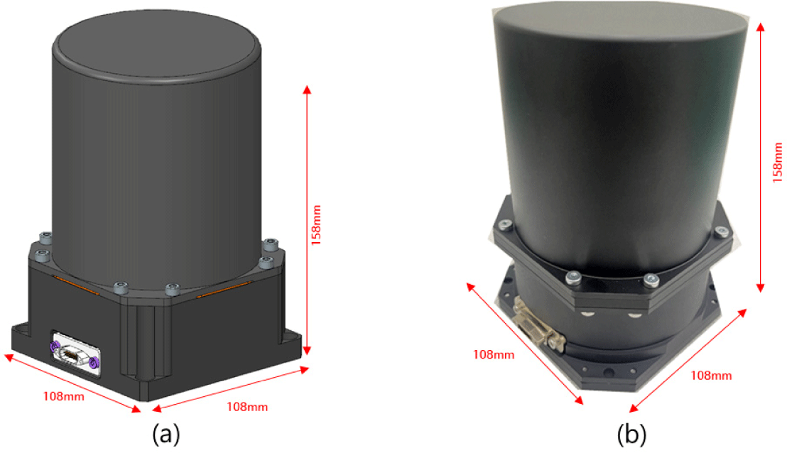
Considering the values in Table 1, where the CMG development target specifications are established, the CMG produced based on these is shown in Fig. 1. The CMG, which is size is 106 mm × 106 mm × 158 mm in size, and weighs 3.5 kg, was developed to be suitable for high-mobility attitude control of microsatellites [2].
3. CMG HW PERFORMANCE TEST
There are various ways to measure CMG performance capabilities. Considering these various methods, in this study, performance was measured using a Kistler Table, which is one of the most commonly used methods for measuring the torque of a rotary motors. Fig. 2 shows the shape of the Kistler Table, which is installed on the granite. A granite plate was built to minimize the effects of vibration and other effects when the CMG rotates at a high speed. The CMG was then assembled on the Kistler Table, and the coordinate axes were defined as shown in Fig. 2 to measure the torque generated from the CMG for each axis.
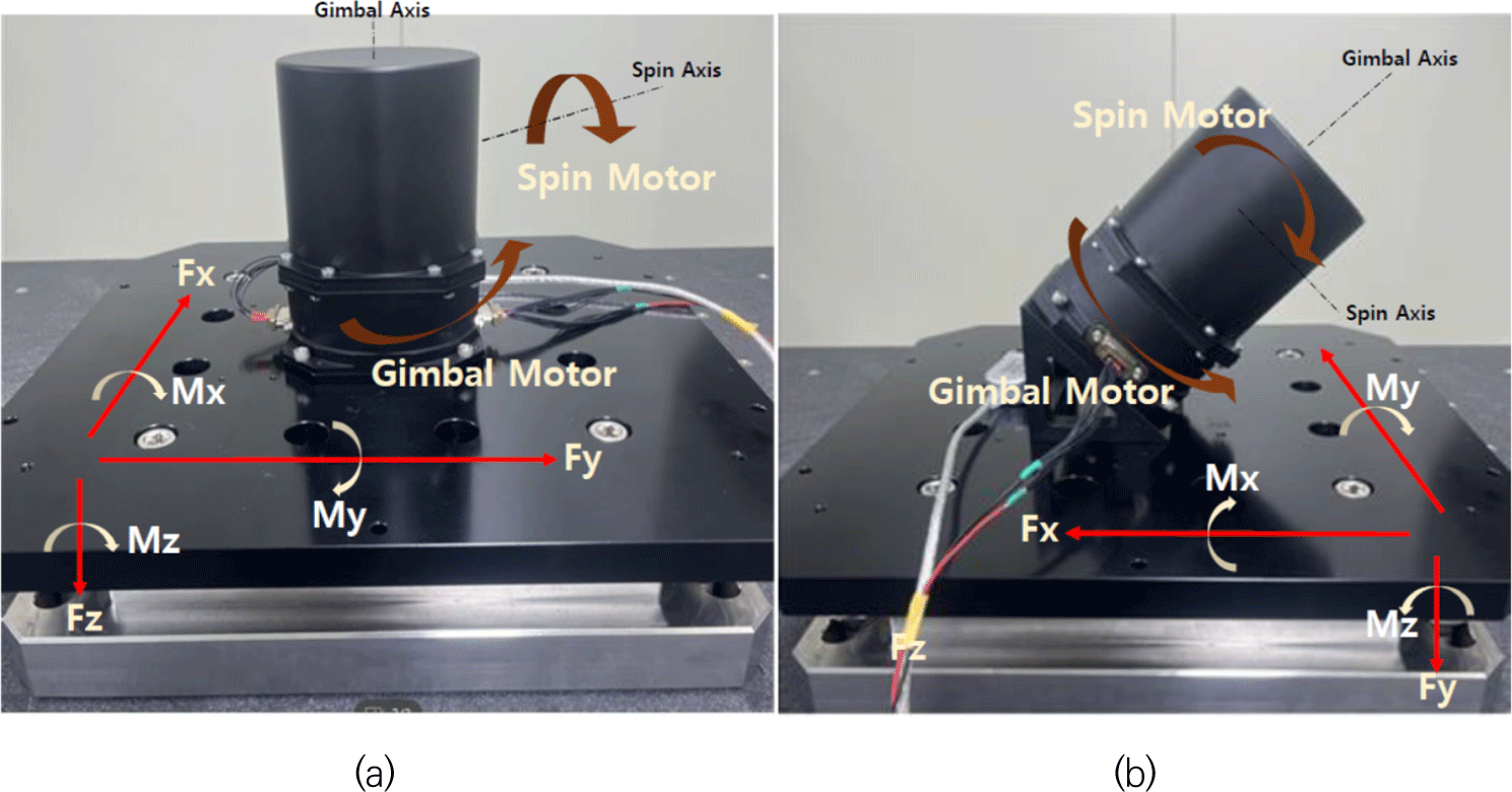
As shown in Fig. 2(a), the CMG was placed in the center on the granite. By locating the CMG at the center of the Kistler Table, the intent is to secure the error between the theoretical values and the actual measured values. Fig. 2(b) shows the assembly shape used to measure the generated torque value, assuming that it is mounted on the actual satellite structure. In the future, individual CMGs will be clustered considering various shapes and should be arranged to generate high mobility torque on the axes required in various shapes depending on the mission.
The interface between the Kistler Table and the surrounding sensor for measuring the CMG torque is shown in Fig. 3 below. The CMG is assembled on the stone surface table, and the Kistler Table is positioned at the bottom. A three-axis accelerometer is installed at the bottom of the CMG. Acceleration information generated during the operation of the CMG is output from the Kistler Table, the output signal is input to a DAQ channel, a signal acquisition device, through an amplifier and stored in the control computer.
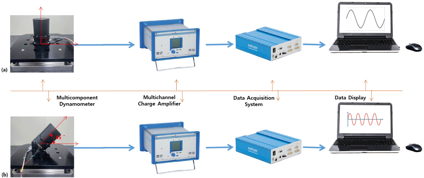
The main components for measuring the CMG torque consist of the Kistler Table, Signal Amplifier, DAQ system, control computer. The main specifications are as follows:
-
- Kistler Table: System with built-in piezoelectric three-component dynamometer
-
- Signal Amplifier: Signal charge and amplification system
-
- DAQ system: Moment calculation for each of the three axes Fx, Fy, Fx in eight channels of the Kistler table’s four piezoelectric three-component dynamometers
-
- Notebook: Displays the measured torque
4. TEST RESULTS AND DISCUSSION
The configuration and axis definition for CMG torque measurement were established in the previous chapter. Based on this, this chapter describes the torque measurement results for the CMG assembly configuration.
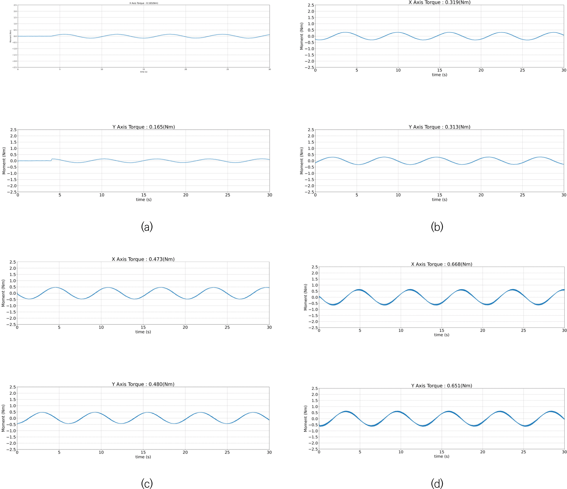
The CMG torque measurement results in a shape assembled at right angles (CMG is assembled vertically with the Kistler table) to the Kistler Table are as follows. When measuring the torque of the CMG, the torque was measured by varying the speed of the spin motor by considering additional operating conditions depending on the nominal conditions and mission. The error with the simulation was also checked (Fig. 4).
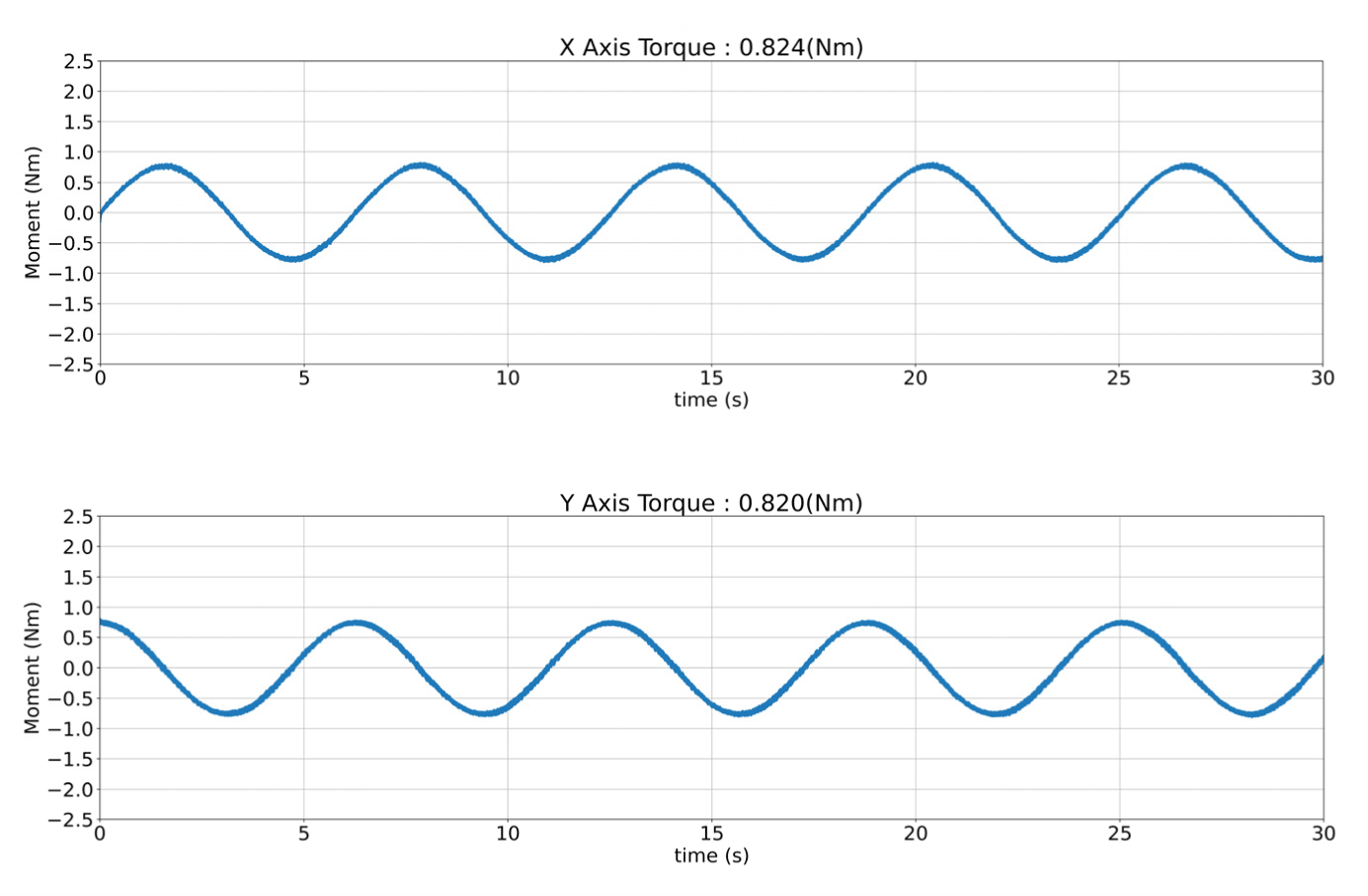
Fig. 5 below shows the speed of the spin motor starting at 1,000 rpm and changing up to 5,000 rpm.
The CMG torque measurement results for the shape assembled at a 45° angle on the Kistler Table are as follows. The performance verification was completed based on nominal conditions when measuring the CMG torque. The Kistler Table and the CMG torque tilted at a 45° angle are a CMG mounting configuration that takes into account the actual mission environment. In this test, considering the operating conditions, the speed of the spin motor was varied from 1,000 rpm to 4,000 rpm and the torque that can be generated by CMG was measured. Fig. 6 below shows the torque generated after setting the speed of the spin motor built into the CMG to 1,000 rpm.
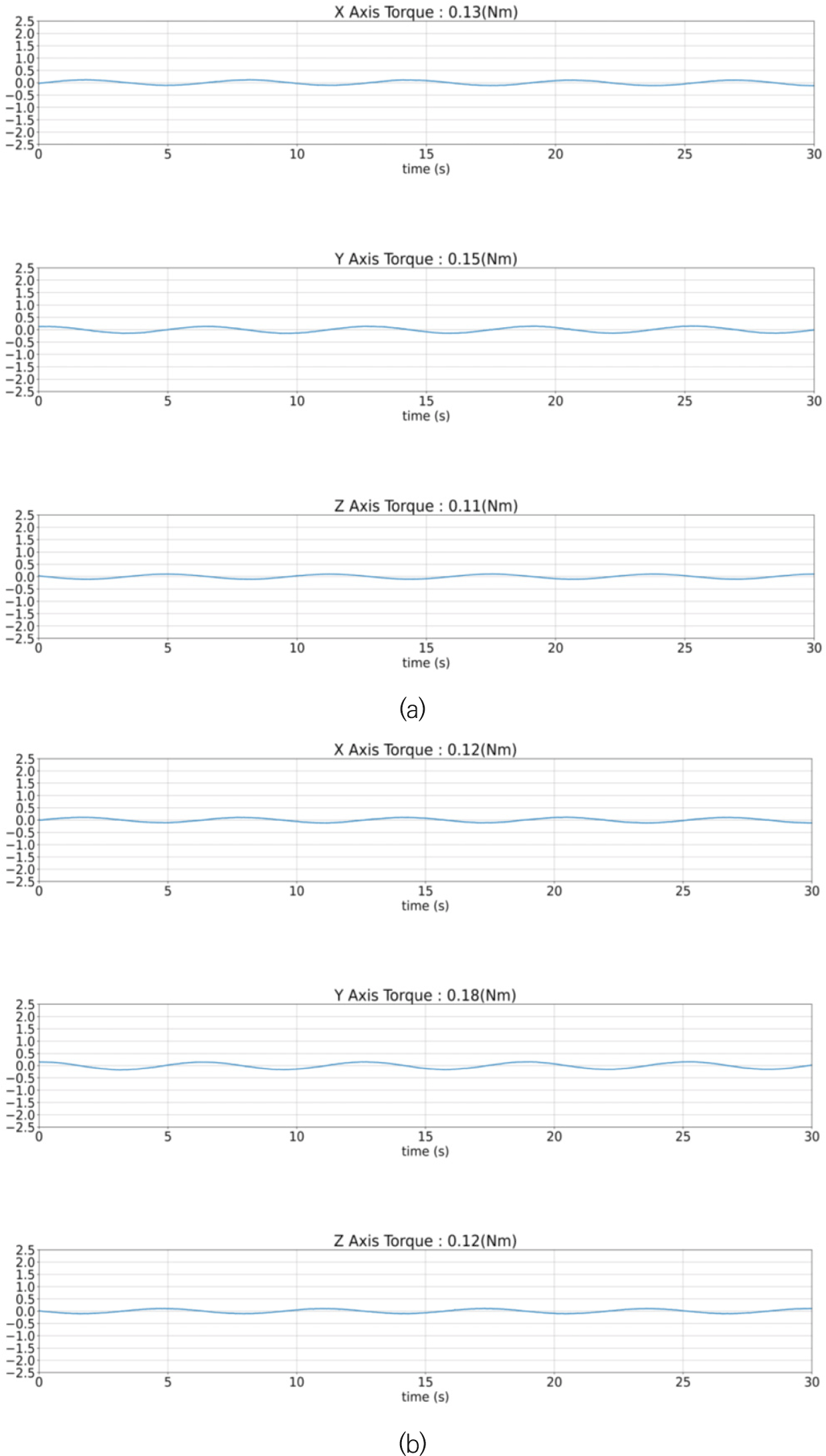
Fig. 7 shows the torque generated after setting the speed of the spin motor built into the CMG to 2,000 rpm. It can be seen that the generated torque increases by approximately 178% compared to that in Fig. 6. This shows that the speed of the CMG spin motor is related to the amount of torque generated.
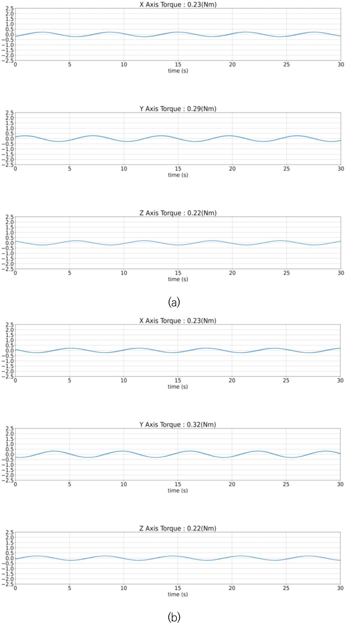
Fig. 8 below shows the torque generated after setting the speed of the spin motor built into the CMG to 3,000 rpm. This figure shows that the generated torque increases by about 168% compared to that in Fig. 7, including that the speed of the CMG spin motor is related to the amount of torque generated.
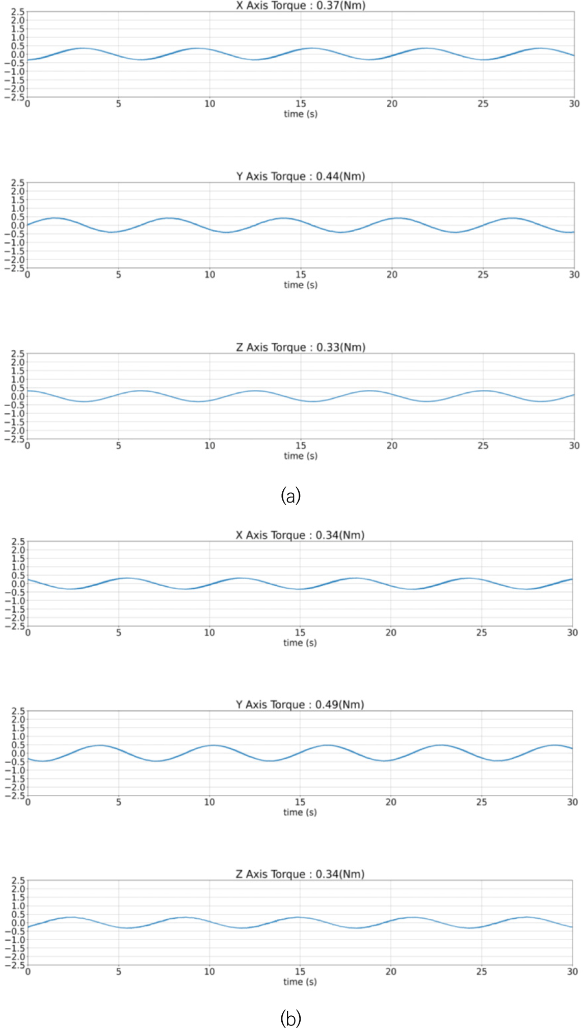
Fig. 9 shows the torque generated after setting the speed of the spin motor built into the CMG to 4,000 rpm. In this case, the generated torque increases by about 157% compared to that in Fig. 8. As above, the speed of the CMG spin motor is related to the amount of torque generated.
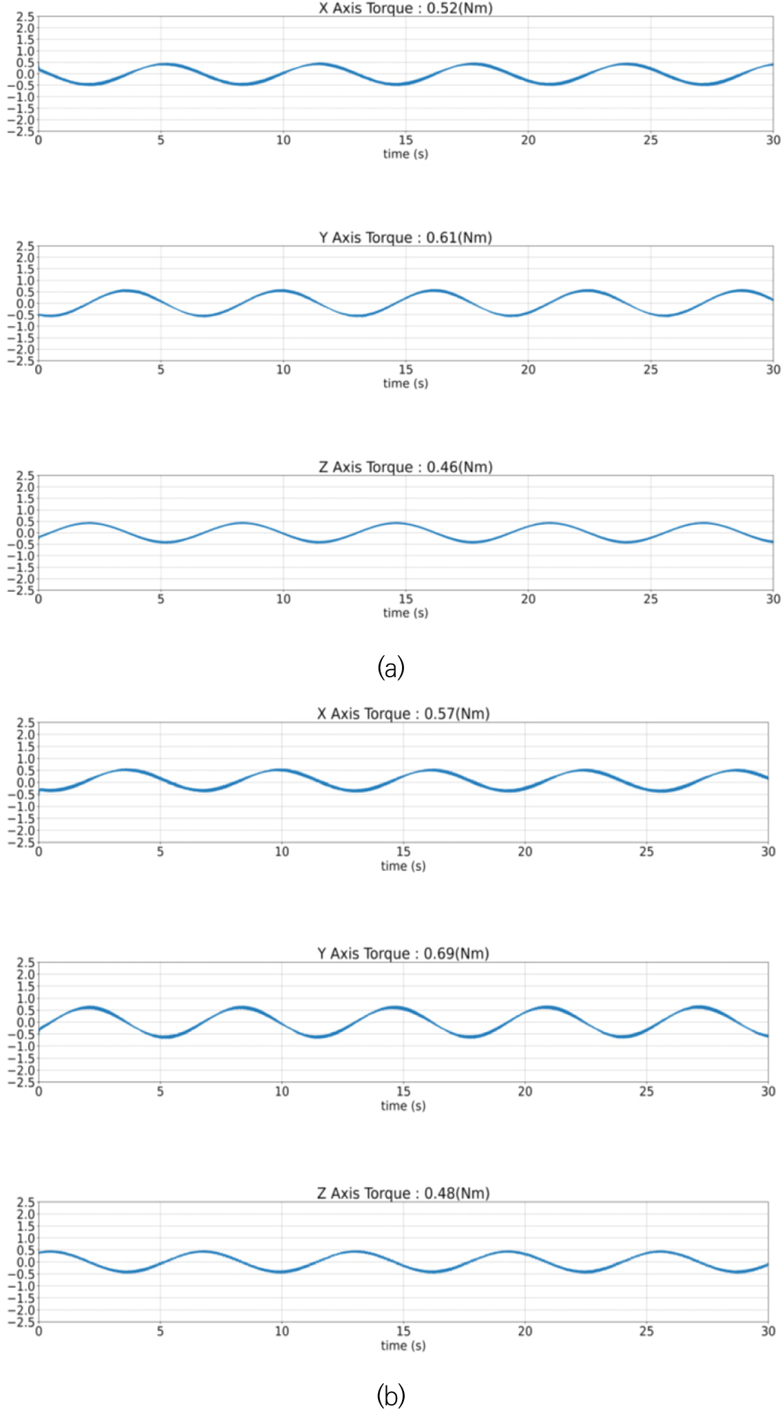
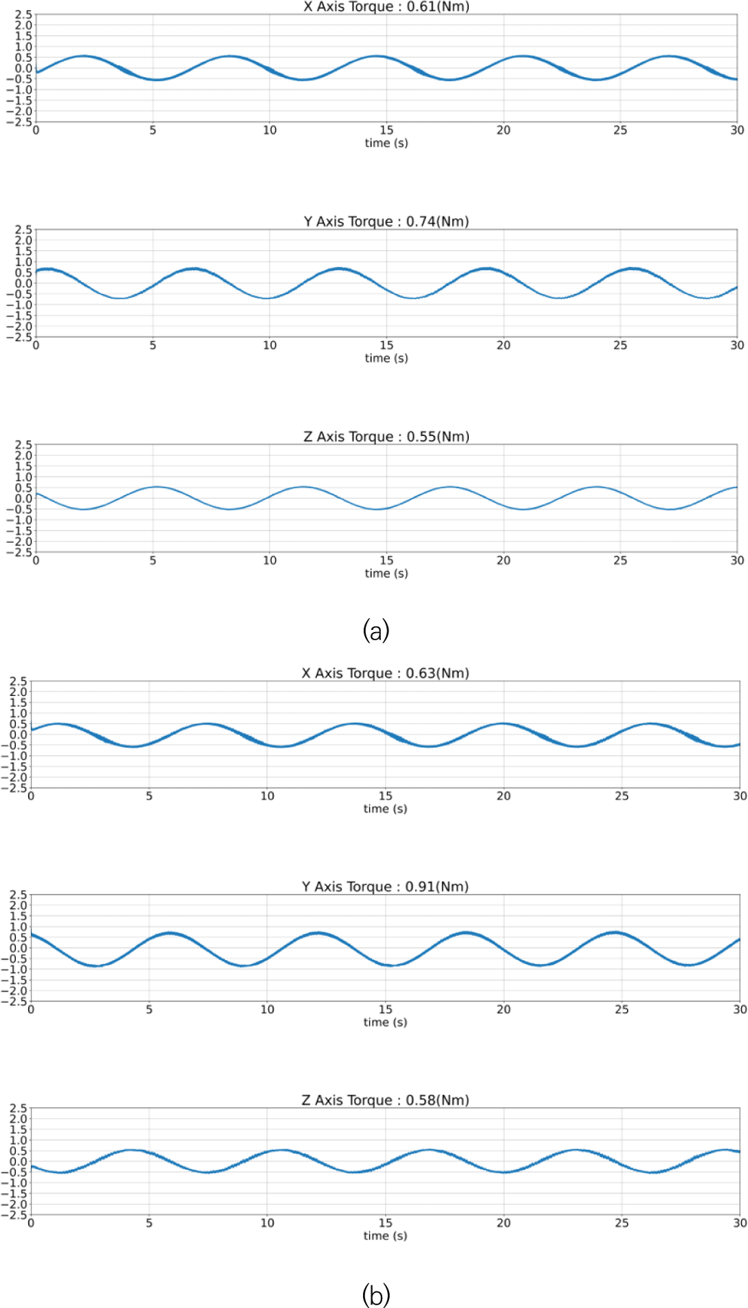
Lastly, the torque generated when the spin motor speed is set to 5,000 rpm in a shape assembled by tilting the angle of the Kistler Table and CMG by 45° is shown in Fig. 10. Fig. 10 below shows the change in the torque on the time axis after setting the speed of the spin motor built into the CMG to 5,000 rpm. Here, the generated torque increases by approximately 117% compared to the previous Fig. 9 indicating that the speed of the CMG spin motor is related to the amount of torque generated.
The power consumption of CMG was measured in two modes. One was measured in stand-by mode and the other was measured when the spin motor’s rotational speed was at maximum. The results of the CMG power consumption are as follows (Table 2).
| Mode | Test results |
|---|---|
| Stand-by power | 1.40 W |
| Peak power at 5,000 rpm | 9.24 W |
5. CONCLUSION
The torque was measured when the CMG was tilted at a 45° angle, taking into account a vertically fastened condition and a clustered condition. When the CMG was vertically fastened, measurements were taken by fastening the CMG to the center of the Kistler Table. Under the condition of fastening the CMG at an angle of 45°, the torque was measured when the center of the CMG’s spin motor was at the center of the Kistler Table and when the center of the gimbal motor was at the center of the Kistler Table. Comprehensive test results of the torque generated according to the assembly angle of this CMG are summarized below. When the CMG was fastened vertically, it was found that the measured torque increased proportionally when driven in stages from 1,000 rpm to 4,000 rpm compared to the nominal condition of 5,000 rpm. Table 3 summarizes the generated torque.
The torque generated by the CMG when the gimbal motor is tilted at 45° is shown in Table 3 below. It was found that as the CMG was tilted by 45°, the moment in the X and Y directions became smaller and the moment in the Z direction became larger compared to those when the CMG shape was assembled at 90°. It was found that the measured torque increases proportionally when driven in stages from 1,000 rpm to 4,000 rpm compared to the nominal condition of 5,000 rpm.


