1. INTRODUCTION
With the rapid advancement of space technology, human exploration in space has become increasingly frequent. In recent years, many countries have proposed large-scale construction of satellite constellations, such as the Starlink Program, OneWeb constellation, and Amazon Kuiper Space Program. These initiatives have the potential to threat the safety of the space environment and the utilization of orbital resources, but also pose significant challenges [1–3]. However, the growing number of space debris resulting from spacecraft abandonment, explosions, and collisions presents a major threat to the safety of spacecraft. According to statistics, the European Space Agency (ESA) has recorded over 630 debris collision incidents, and the U.S. military estimates an average of 21 potential space conflict accidents per day. Currently, there are more than 30,000 large fragments (over 10 cm in diameter) in space, with even higher numbers of medium and small fragments [4,5]. This poses a serious risk to the normal operation of spacecraft in orbit. To mitigate the impact of debris on spacecraft, protective nets are often used, but they can only withstand large debris and are not effective for smaller fragments. As a result, many foreign scholars have proposed debris removal plans to reduce the risk of space debris collisions with spacecraft. For example, the German space agency and NASA plan to use laser ablation to remove large debris, using ground-based or space-based lasers to emit high-energy pulses to disintegrate debris near the spacecraft. The ESA has also proposed mechanical capture methods, such as harpoons and flying nets, to remove space debris [6–9]. However, the success of these methods relies on accurate real-time measurement of debris targets. Debris laser ranging (DLR) technology is an effective means of detecting debris targets. It involves emitting laser pulses to the debris and measuring the round-trip time between the ground station and the debris to determine the distance, allowing for real-time measurement of space debris. This technology can help ground stations monitor the movement of debris and reduce the risk of collisions with spacecraft.
In order to effectively monitor debris targets, various international stations are actively developing space DLR technologies. Significant progress has been made in the observation period, detection band, and measurement frequency. For example, in 2017, the German Wettzell station, the Stuttgart station, and the Austrian Graz station conducted joint measurements of non-cooperative targets using 532 nm and 1,064 nm dual-wavelength lasers. They were able to measure distances of up to 3,000 km and detect debris with a minimum scattering area of 0.4 m2 [10]. In 2019, the Graz observatory used a nanosecond laser system with a repetition frequency of 200 Hz and an output power of 16 W to successfully measure over 40 rocket fragments during the daytime [11]. Similarly, in China, the Shanghai Observatory used a nanosecond laser with a repetition frequency of 20 Hz and an average power of 40 W to conduct the first space debris measurement in 2008. Other stations, such as the Yunnan Observatory and Changchun Renwei Station, have also completed successful detection of space debris and obtained valuable measurement data [12,13]. However, the current space debris ranging technology relies on a kHz nanosecond laser light source with an average power of about ten watts, which limits the detection ability and accuracy of the system[14]. To address this issue, the Shanghai Observatory has developed a kHz pulse frequency debris measurement system to achieve high-precision detection of longer-range and smaller targets[15,16]. This system is based on the satellite laser ranging system of the Shanghai Observatory and uses a picosecond laser with a central wavelength of 1,064 nm and a repetition frequency of 1 kHz as the emission light source, with an average output power of 30 W. The goal is to conduct the laser ranging experiments on space debris at different orbital heights.
2. SPACE DEBRIS RANGING SYSTEM
The schematic diagram in Fig. 1(a) shows the kHz high-power picosecond laser. The laser consists of four main parts: I) the semiconductor saturable absorber mirrors (SESAM) mode-locked cavity, II) the volume Bragg grating (VBG) pulse broadening and beam splitting section, III) the regenerative amplifier, and IV) the traveling wave amplifier and frequency multiplier. In the SESAM mode-locked cavity, a laser diode (LD)-pumped Nd:YVO4 crystal is used to produce picosecond pulse seed light with a central wavelength of 1,064 nm. This seed light then enters the section II for pulse broadening and beam splitting using optical range difference. The VBG is responsible for broadening the pulse width to prevent damage to optical components during amplification. The beam is then split into two beams by the beam splitter BS1. These two beams are further split by the BS2 and BS3, resulting in four beams of light pulses. These pulses are reflected by M01–M04 and combined in BS1 to produce a burst pulse string composed of four pulses. The section III is the regenerative amplifier cavity, which amplifies the energy of the burst pulse string using a Nd:YAG gain medium. The injection and output of pulses in the cavity are controlled by adjusting the laser polarization state. The amplified laser light is then reflected into the two-stage single-pass wave amplifier by P3. The two modules, MD2 and MD3, are LD-side-pumped Nd:YAG modules, and AR1–AR3 are concave lenses used to compensate for the thermal lens effect of the crystals [17].
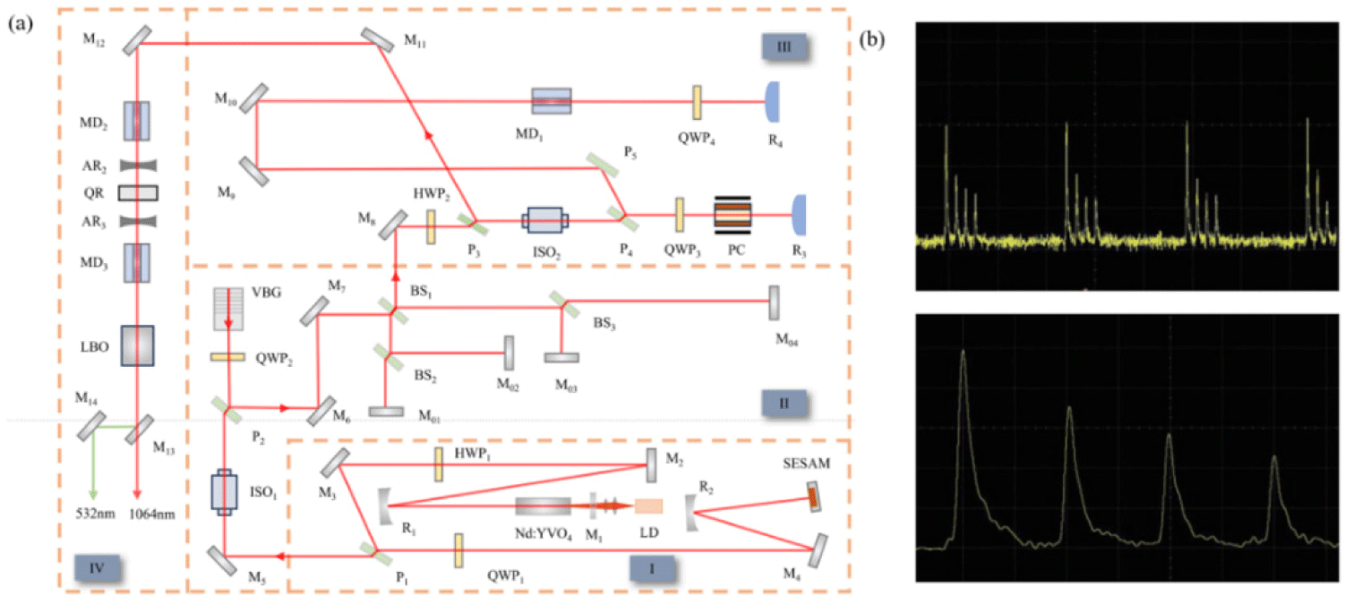
Fig. 1(b) illustrates the burst waveform, which is composed of four pulses. Each pulse corresponds to the waveform returned by M01–M04, with the spacing of each pulse representing the time interval corresponding to the optical range difference of each path. The amplitude of each pulse varies due to the different energy loss of each beam at the beam splitter mirror. By adjusting the pump current, a 1,064 nm laser output with a pulse width of approximately 100 ps, a repetition frequency of 1 kHz, and an average power of 30 W can be achieved.
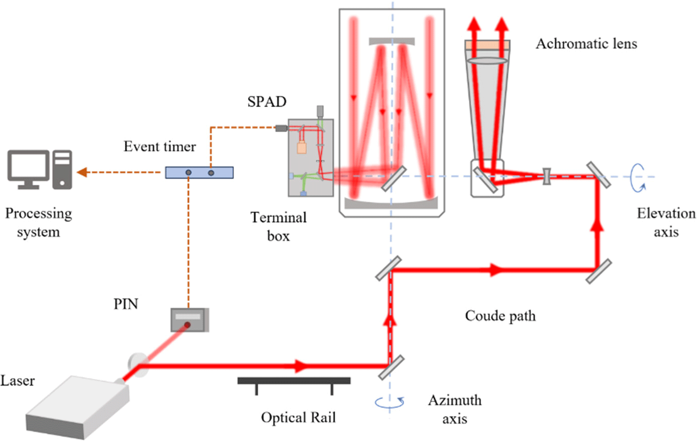
The telescope has a transceiver-separated optical structure, with separate apertures for laser emission and reception. The optical transmission system, shown in Fig. 2, consists of the folded-axis optical path, the emission optical path, and the reception optical path. It is capable of performing laser ranging in the 532 nm as well as 1,064 nm wavelength bands. The transmitting optical path has a 14 cm aperture, and the pulsed laser is collimated on the optical rail before being introduced into the Coude folded-axis optical path of the telescope through a 45° reflector. It is then transmitted to the space debris target through the outgoing mirror tube after undergoing 6-fold beam expansion. Additionally, an achromatic lens is placed in front of the transmitter tube to compensate for chromatic aberration at 1,064 nm. The signal from space targets is received by a 60 cm telescope, which passes through a Cassegrain telescope system and is reflected by a third mirror into a terminal box for reception.
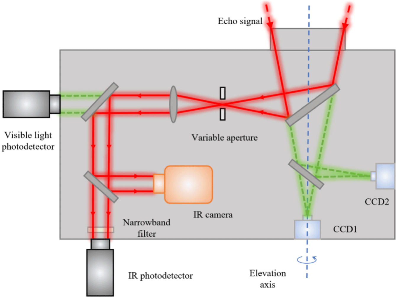
The terminal receiving system is responsible for receiving and detecting the echo signal in infrared fragmentation laser ranging experiments. In order to do so, the terminal optical path needs to be modified by adding an infrared detection optical path to the original visible light detection system. This structure is shown in Fig. 3. The echo signal comes into the terminal box and then passes through an adjustable diaphragm and collimating lens. A portion of the beam then enters the infrared camera, which monitors the position of the star and the beam in real-time. The remaining beam passes through a narrowband filter and enters the infrared photoelectric detector. The optical signal is then converted into an electrical signal and uploaded to the computer system. The narrowband filter is used to filter the spectral properties of the echo signal, with a central transmission wavelength of 1,064 nm and a spectral bandwidth of 2 nm. This helps to reduce interference from environmental noise. For the experiment, a single-photon infrared detector with a receiving target surface of 500 μm, a central detection wavelength of 1,064 nm, a detection efficiency of 20%, low time jitter, and good stability is selected. This allows for high sensitivity and high-precision detection of the echo signal.
3. DEBRIS MEASUREMENT EXPERIMENTS
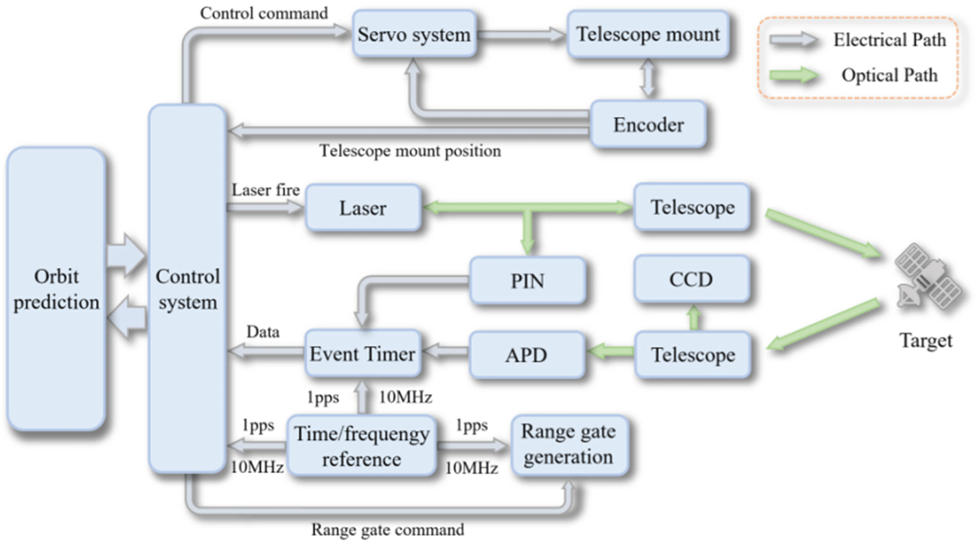
The Fig. 4 shows the space target laser ranging system. In order to obtain accurate information about the debris orbit, the debris ephemeris is first downloaded from the Space-Track website of the North American Air Defense Command (NORAD) and converted into debris orbit prediction files on the computer. The control system then uses these prediction files to adjust the orientation and height of the telescope frame in real-time to track the target. When the control system gives the ignition command, the laser is split into two beams - one enters the main wave detector and the other is launched through the telescope. The main wave detector uses a PIN photoelectric detector to collect the optical signals at the launching end and transmit the moment value of the main wave to the event timer. The return echo is transmitted to the terminal receiving system through the receiving telescope, where it is collected and processed by a single-photon detector. The event timer records the arrival moment of the echo signal and uploads the reception moments of the main wave and the echo to the computer. The computer then calculates the distance of the target debris using the difference of the laser round trip time and the speed of light. The time-frequency system is responsible for synchronizing the local time with the coordinated universal time (UTC) and also provides a high-precision time-frequency reference for the entire ranging system. The control system outputs a gating signal to control the detector’s opening time, allowing it to receive the echo signals before their arrival and minimizing the interference of ambient noise.
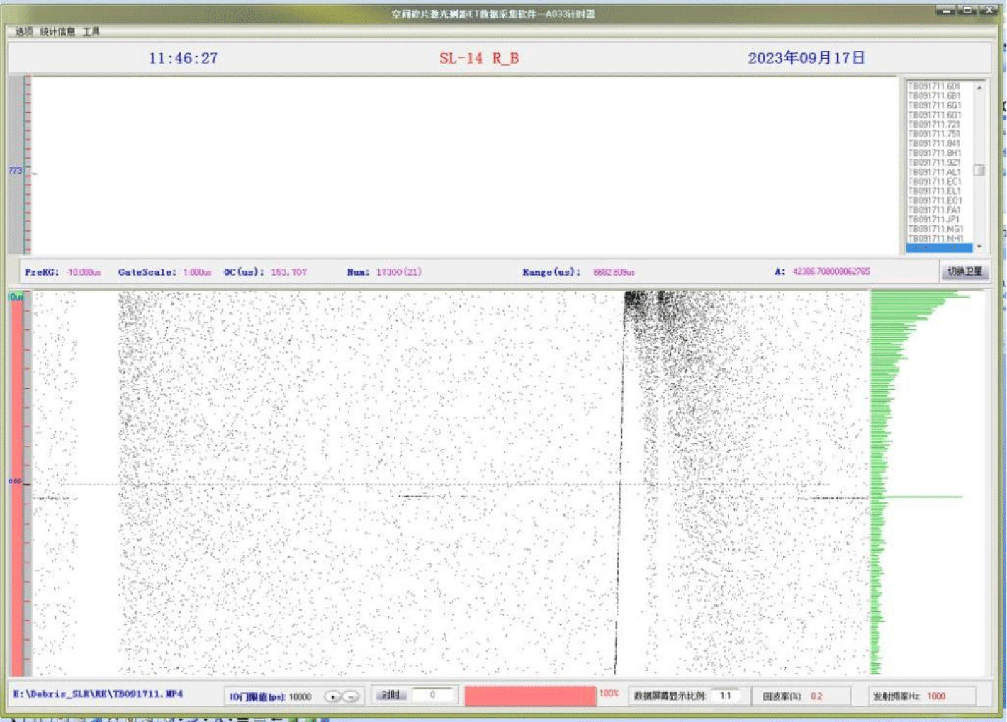
When preparing to observe a target’s transit, the tracking control software is used to guide the telescope in real time. Once the tracking camera confirms stable tracking, the laser is fired at the target. Simultaneously, the camera is used to align the laser light with the debris target and adjust both to the camera’s sensitive area for accurate tracking measurements. During the measurement process, the acquisition software interface displays both the echo signals and noise points. Fig. 5 depicts the echo acquisition interface for measuring target THOR_R_B (No. 25163). The points in a linear shape represent effective echo points, while the remaining points are considered noise. The intensity of the echo signal can be adjusted by continuously fine-tuning the position of the target and optical tip. Once the measurement is complete, the data processing software is utilized to analyze the data and obtain information such as the return echo rate of the target fragments and the measurement accuracy.
4. RESULTS AND ANALYSIS
We conducted measurements of debris targets at various altitudes using the ranging system. A total of 240 laps of observation data were obtained, with 60 laps being jointly measured by multiple stations. Table 1 shows some of the measurement data for the debris targets. The second column displays the corresponding NORAD number, while the third column shows the farthest distance of the debris target. The fifth and sixth columns indicate the measurement accuracy and radar scattering cross-section product [radar cross section (RCS)] of the debris, respectively. The last column displays the RCS size when the debris is equivalent to 1,000 km. We have included measurements with equivalent RCS values ranging from 0 to 1 m2.
Based on the high-power kHz infrared ranging system, we have successfully collected data on 36 debris observations with an equivalent RCS lower than 0.1 m2, with the smallest RCS being 0.04 m2. Additionally, we have observed six debris targets with an RCS lower than 1 m2. Our results, as shown in Table 1, demonstrate a detection accuracy of approximately 2 cm for the abandoned satellite SICH_2 (Gz) (No. 37794). Furthermore, we have analyzed the measurement accuracy and detection range of the debris, as depicted in Fig. 6. The figure illustrates the distribution of measurement accuracy and detection distance with respect to RCS. Our findings indicate that the majority of debris targets have a size of 4–6 m2 and a detection range of 500 km to 2,000 km. The root mean square (RMS) measurement accuracy is mostly below 200 cm. Notably, the debris target GONETSM_03 (No. 38734) has a detection distance exceeding 2,500 km with an accuracy of approximately 2,000 cm. This target’s detection range is at the meter level.

From the experimental results, the use of burst pulse train composed of 4 pulses can realize the measurement of more distant targets. At the same time, the combination of the ranging advantage of the infrared band and the nonlinear effect of high-power picosecond laser pulses in atmospheric transmission makes the ranging system based on the burst-mode infrared picosecond laser to achieve a better detecting capability compared with the conventional single-pulse nanosecond laser ranging system.
5. CONCLUSION
High-precision space DLR technology is a crucial means of obtaining real-time information on space debris movement, providing a vital basis for spacecraft collision avoidance and debris removal in orbit. In this paper, we addressed the development of a 1,064 nm infrared kHz picosecond laser ranging system, with an output power of 30 W, based on the satellite laser ranging system at Shanghai Observatory. This is the first time such a system has been built. We demonstrated successful measurements of space debris targets at various altitudes, obtaining 240 sets of observation data with a detection range of up to 2,500 km and an equivalent RCS of 0.04 m2 at 1,000 km. The ranging accuracy is up to the centimeter level, establishing a new method for high-accuracy ultra-high-frequency DLR. The average measurement accuracy is at the decimeter level, laying the foundation for subsequent high-precision laser ranging of ultra-high-frequency debris.

