1. INTRODUCTION
Space debris has been a potential threat to space missions and human space activities because its collision probability is increasing due to the exponential growth of space debris population. The spatial density of orbiting objects is so sufficiently high that a collision would cause a collisional cascading problem known as Kessler Syndrome [1] unless any action is taken to decrease the amount of space debris, such as anti-collision maneuver and space debris removal.
The two line elements (TLE) catalogue of space debris is generated and maintained by the US Air Force using radar and passive optical tracking data for various orbit propagation tasks. But it is often found that the TLE catalogue does not provide the required orbit accuracy for the space debris collision warnings, for example, the collision between the Iridium 33 satellite and the defunct Cosmos 2,251 on February 10, 2009. Improving the orbital prediction accuracy is necessary to prevent collision against space debris, or to avoid unnecessary anti-collision maneuvers of operational spacecrafts.
The accurate orbital prediction is achievable using the combination of optical and laser tracking data obtained even from a single station through the estimation of ballistic coefficients [2–5]. In contrast to the satellite laser ranging (SLR) of cooperative targets with laser retro-reflector array (LRA), the laser ranging of space debris requires higher laser power because of low reflectivity of uncooperative target without LRA. The ranging precision is in range of 30 cm to 230 cm [6–8], resulting from space debris size and large laser pulse width of nanoseconds. Even though the debris laser ranging provides accurate measurements with one or two orders of magnitude better than the radar and passive optical tracking system, the dynamic model should take into account the debris characteristics such as size, shape and orientation information in order to improve the orbital prediction precision. The debris characteristics will influence the accurate orbital prediction as non-gravitational perturbations such as atmospheric drag and solar radiation pressure are heavily influenced by them [9]. They are available from high resolution images by ground-based optical telescope. But the image is highly distorted by atmospheric turbulence to such an extent that the image may not be often recognizable.
Adaptive optics (AO) is a technology to improve the image quality by compensating the global tilt and the local phase fluctuations for the incoming wavefronts distorted by atmospheric turbulence. It provides the high resolution image of space objects including active satellites and space debris, close to the diffraction limit of an optical telescope. Currently, AO technologies have been increasingly used for space situational awareness (SSA), particularly in the field of the space object imaging and identification, space debris laser tracking (DLT) and space debris removal [10-15].
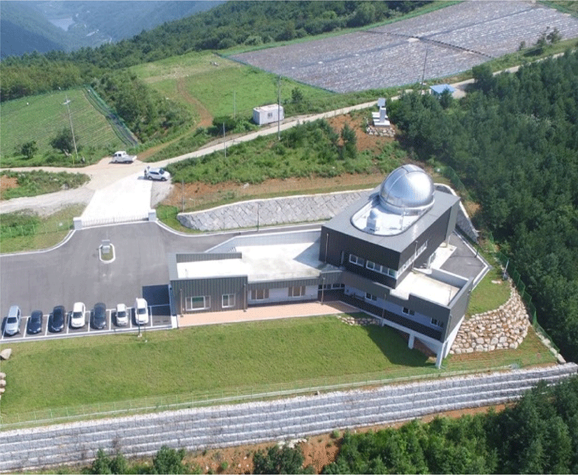
Korea Astronomy and Space science Institute (KASI) established the space optical and laser tracking (SOLT) system at Geochang observatory for space geodesy, SSA and Korean space missions [16]. Fig. 1 shows the external view of Geochang observatory located at 950 m above the sea level. The SOLT system consists of three systems sharing an optical telescope with 100 cm clear aperture: SLR, AO, and DLT. The AO system is designed to be capable of imaging the space objects brighter than 10 magnitude using space objects as a natural guide star. It will provide space object information such as size, shape and orientation which are available from the characterization and identification process based on the AO high resolution imagery. To develop the AO system KASI specified the site characteristics, design performance, and some critical parameters. The Australian National University (ANU) designed, build, and installed the AO system including initial operations to successfully demonstrate its capabilities. In this paper, we present the design and development of AO system which was implemented at the Geochang observatory. In addition, it is demonstrated that the AO system provides the good stellar images with a near diffraction limit and shows good performance in terms of the full width at half maximum (FWHM).
2. DESIGN OF ADAPTIVE OPTICS SYSTEM
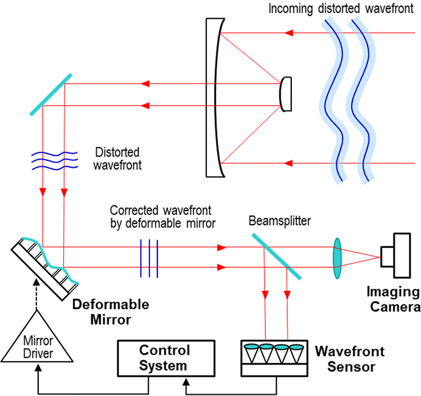
Light propagation through the atmosphere is inevitably aberrated by atmospheric turbulence which degrades image quality obtained with a ground-based optical telescope. The AO measures the distorted wavefront using a wavefront sensor (WFS), and then compensates the atmospheric turbulence in real time by controlling an active optical element such as a tip-tilt mirror and deformable mirror (DM) in order to provide the high quality image of space objects. As shown in Fig. 2 illustrating the AO operational principle, the AO system consists of a WFS, a DM, a control system and an imaging camera. A dichroic beamsplitter is used to split the incoming beam into two beams, depending on the wavelength and then transmit the beam to the WFS and the imaging camera, so that wavefronts are measured at the same time when images are taken.
The AO design is seriously determined by the telescope size and atmospheric conditions at the site. So the AO system of the Geochang station is designed to image the space objects brighter than 10 magnitude up to 1,000 km using the 100 cm telescope, and achieve a Strehl ratio larger than 20% in the environment of good seeing with coherence length (or Fried parameter) of 12 to 15 cm and wind speed of 8 to 10 m/s. The AO system is also designed to use the sunlight of the visible wavelength range reflected from space objects as the natural guide star light for the wavefront measurement, and the infrared wavelength range for imaging.
Light from the optical telescope is directed to one of three systems (i.e., SLR, AO, and DLT systems) by switching a Coudé mirror inside the telescope pedestal. The SLR, AO, and DLT systems are installed on an optical bench in a temperature and humidity controlled Coudé room, respectively. Seven Coudé mirrors including the primary and secondary mirrors are coated against a high power laser for DLT operation. The optical telescope is designed using a parabolic primary mirror with 100 cm clear aperture and focal ratio of f/1.5, and a parabolic secondary mirror with 25 cm clear aperture. It provides a diffraction limit of 0.18 arcseconds at 850 nm wavelength which will be able to resolve features 85 cm in size for space objects at the distance range of 1,000 km.
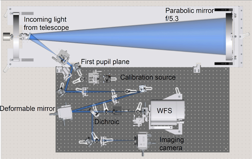
Fig. 3 shows the optical schematic of AO system. The collimated beam with 250 mm diameter via Coudé path is reduced into 12.5 mm by an on-axis beam expander with a f/5.3 parabolic mirror and a collimating lens, and then reflected off the DM to the dichroic beamsplitter. The light is split by the beamsplitter, making the light of wavelengths from 450–800 nm pass to the WFS, and the light of wavelengths from 800–1,000 nm reflected to the imaging camera. The WFS has also a beam expander which converts the beam from 12.5 mm to 2.5 mm, which consists of three lenses, the first two forming a compound lens to adjust the precise size of the beam. The pupil is also relayed, making the DM conjugate to the lenslet array, which also corresponds to the telescope pupil. A calibration source is also inserted onto the AO optical bench to calibrate the AO system setup and to optimize the performance between the DM and the WFS, which is applicable by a mechanical flip mirror.
The AO system uses a Shack-Hartman WFS consisting of a lenslet array with 8 × 8 subapertures and a OCAM2K camera available from First Light Imaging which uses an electron-multiplying charged-coupled device (EMCCD) sensor. The lenslet array has a pitch of 300 μm and a radius of curvature of 9.5 mm which achieves a pixel scale of 0.6 arcseconds per pixel. The OCAM2K camera has 240 × 240 pixels and can be operated up to 2,067 frame per second (fps) with sub-electron readout noise (< 0.3 e– at 2,000 fps and 600 multiplication gain). It also offers an extremely low latency allowing high speed operation: 43 μs between exposure and first pixel availability. The OCAM2K camera is cooled to –45°C with liquid cooling and a thermoelectric cooler in order to prevent sensor damage by over illumination, and also has firmware protections to minimize the risk of over illumination.
The DM is an ALPAO DM97-15 which has 97 actuators, maximum pupil diameter of 13.5 mm, a large stoke of actuators in range of up to 30 μm for tip-tilt, and large bandwidth up to 2 kHz with 45 degrees of phase lag. The large stoke and bandwidth allows the AO system to compensate atmospheric turbulence without a fast steering or tip-tilt mirror for high-order aberration correction. The actuators are arranged in a 11 × 11 grid with a spacing of 1.5 mm. With a clear aperture of 13.5 mm, only 9 × 9 actuators are in the visible area, whereas the outer ring of actuators are extrapolated for stability of the mirror edge.
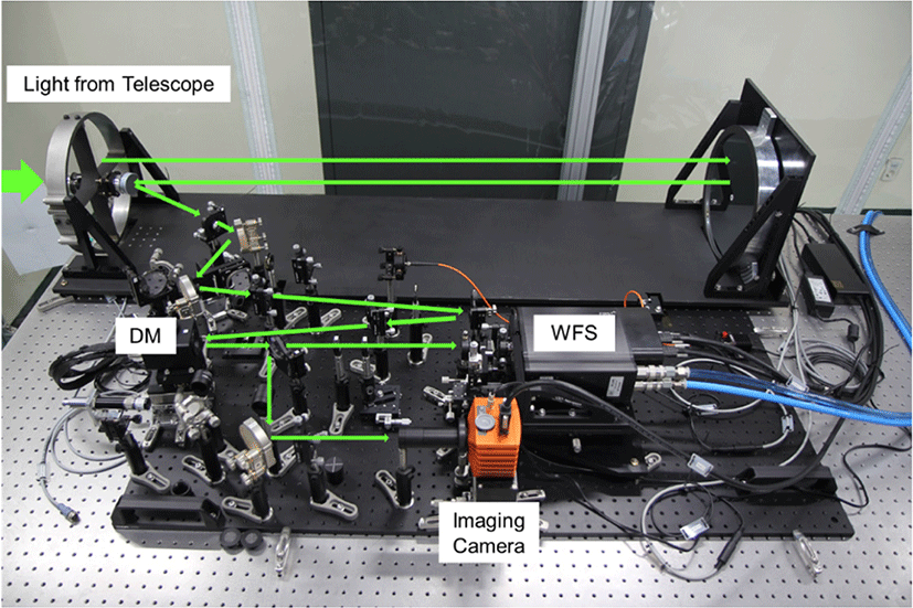
The imaging camera is fed with corrected wavefronts in real time, which includes the camera optics and imaging detector. The Raptor Falcon EM285-CL of imaging camera has a EMCCD sensor with 1,004 × 1,002 pixels, 64 mm2 of active area, and can be operated up to 30 Hz (Table 1). The image derotation is done by post-processing software combined with lucky imaging and imaging data so that a mechanical derotation device is not necessary. Fig. 4 shows the AO system established at Geochang observatory.
The AO closed loop control system hosted on an real-time computer (RTC) ties together the WFS, DM, imaging camera, and telescope offsets to maintain satellite tracking and perform AO correction (Fig. 5). A custom software server controls all electronic components of the AO system including LED calibration source with variable brightness, flip mirror to switch between calibration and sky, imaging and WFS cameras, DM, and telescope control.
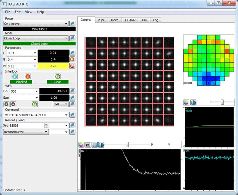
Safety interlocks for several systems are controlled by the RTC to assist the controller in avoiding damage to AO system components. Safety is critical for the continued operation of the DM, and WFS and imaging cameras. The DM has limits on the inter- actuator stroke which must be considered in the control loop as it is an additive process, with each step incrementing on the last. Constraints are required therefore to make sure that the representation of the DM shape in the RTC for computation of the next frame is sufficiently close to the actual DM shape, as there is no electrical feedback from the DM control electronics.
Both cameras are EMCCD, which uses a high-voltage gain amplifier to increase the signal without adding additional readout noise to the camera. If over-exposed, these gain regions can be damaged by the high current throughput, and so over-illumination can be dangerous. To assist the operator in recognizing these dangers and possible situations where damage may occur, the RTC has interlocks on the control loop gain, and EM gain of the cameras. If a dangerous situation should occur such as loss of light from subapertures due to sudden misalignment or something blocking the beam, the control loop will be suspended. If either of the cameras should receive too much light, their gain will be set to 1 to minimize the danger. These interlocks are reported in the log and must be manually reset using the graphical user interface (GUI) to continue operation. During normal operation they are typically not triggered.
Data from the WFS is decoded and split into subapertures, and calibrated for camera bias and sky background. A centre of gravity computation is done on each subaperture to determine the slope. A software-based windowing mechanism allows the system to increase its performance when the seeing is good: the controller can select to narrow down the subapertures, reducing the number of pixels in each subaperture. This reduces the background noise otherwise present when using a centre of gravity calculation. This parameter is user-selectable in real-time, allowing the controller to optimize the AO system performance based on current atmospheric conditions.
DM commands are computed from an interaction matrix using the computed slopes. Commands are sent to the DM on a zonal basis, where each actuator is commanded individually. The closed loop control system uses a leaky integrator with user selectable gain and leak values, and includes spatial filtering to prevent the DM from entering modes which are not measureable by the WFS. Tip-tilt modes are filtered on a temporal basis and fed to the telescope control system to maintain pointing towards the observation target.
The AO system design includes a remote controllable flip mirror and variable intensity LED source to provide hands-off calibration of the system (that is: no-one needs to enter the laboratory and physically touch anything to perform the calibration). These calibration runs can be used to track alignment changes over time, aid in aligning the system, and provide up-to-date interaction matrix for optimize the system performance.
3. RESULTS AND PERFORMANCE ANALYSIS
The performance of AO system implemented at the Geochang observatory with a 100 cm optical telescope is analyzed using two stellar sources, faint and bright stars. The astronomical seeing of general sky conditions at the Geochang observatory is in the range of 2 to 3 arcseconds, which is dependent on the degree of atmospheric turbulence.
The AO system was tested for the faint and bright stars with the visible magnitude of 9.4 (V band) and 1.25 (V band), in order to analyze the AO performance depending on the brightness of a natural guide star. Figs. 6 and 7 show the stacked images of the faint and bright stars, without the AO correction and with the AO correction, respectively. The images are obtained using the lucky imaging algorithm in which the image rotation motion can be also removed. It is shown from Fig. 6 and 7 that the AO correction makes the stellar light to be concentrated in very small number of pixels, compared with stellar images without the AO correction. The diffraction ring is shown in the right images obtained by the AO correction and the lucky imaging algorithm.
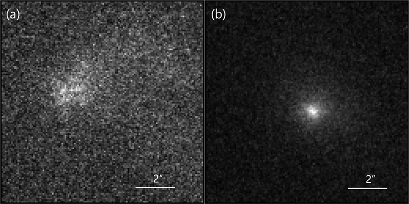
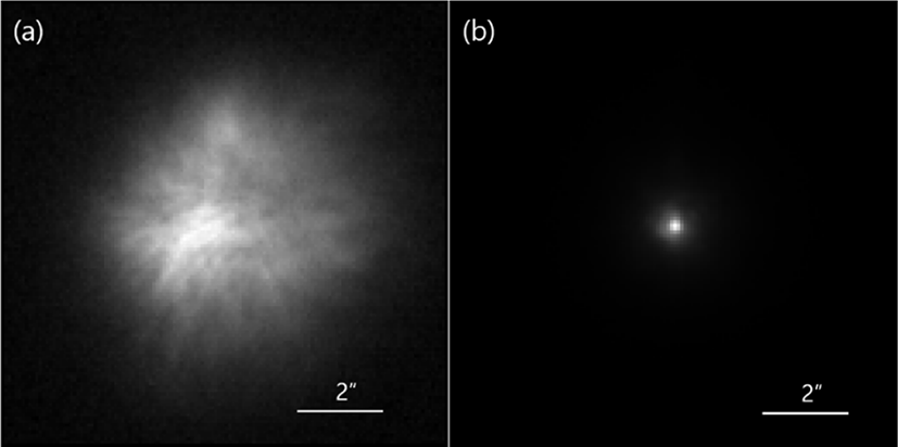
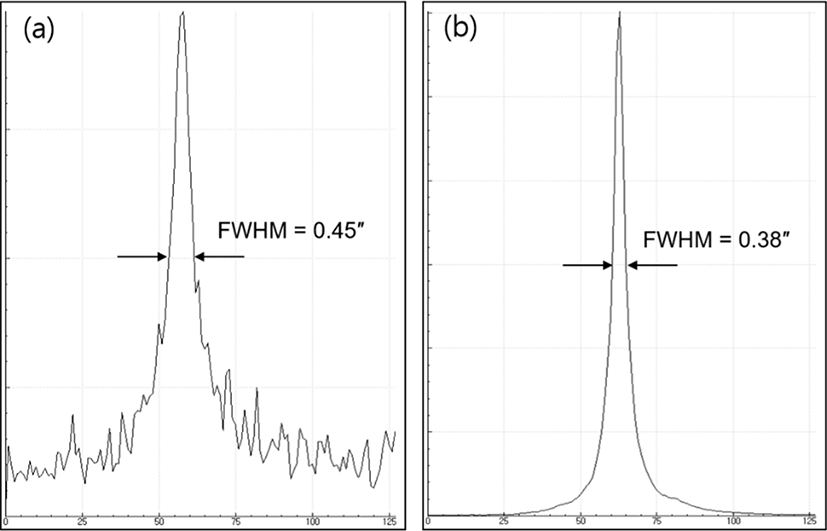
Fig. 8 shows the image profiles with FWHM of a stacked image with the AO correction for the faint and bright stars. The x-axis means the number of pixels and the y-axis is the intensity which also depends on the camera gain. For the faint star, FWHM of the stellar profile is 2.2 arcseconds without the AO correction, whereas FWHM is 0.45 with the AO correction. In the case of the bright star, FWHMs of the stellar profile are 1.9 arcseconds without the AO correction and 0.38 arcseconds with the AO correction, respectively. It was demonstrated from the stellar observations that the AO system at Geochang observatory could mitigate effectively the atmospheric turbulence and result in the good stellar images, by approximately 5 times improvement in terms of FWHM of the stellar image profile.
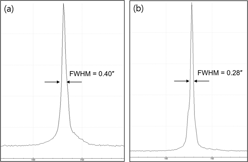
It is necessary to analyze the AO performance in terms of a single image enhancement, instead of a stacked image. Fig. 9 shows the image profiles with the largest and smallest FWHM of single images with the AO correction for the bright star, which are used in the stacked image shown in Fig. 7(b). In the case of the faint star, it was impossible to obtain FWHM value from a single image due to the weak stellar light. The single images with the AO correction have FWHMs in range of 0.28 arcseconds to 0.40 arcseconds, in which most FWHMs are smaller than the stacked image. In general, FWHM of a stacked image is larger than a single image because many images are accumulated in a single stacked image.
4. CONCLUSION
KASI in partnership with ANU developed the AO system which is capable of imaging the space objects up to the altitude of 1,000 km by using themselves as a natural guide star. The AO system was implemented at the Geochang observatory with the optical telescope of 100 cm clear aperture for SSA and Korean space missions.
In this study, the AO system was addressed and its performance was also demonstrated using two stellar sources, faint and bright stars. The AO system is designed to use the sunlight reflected by space objects as a natural guide star, measure the distrorted wavefronts with the WFS and then correct them using the DM with the large stroke, without the tip-tilt mirror. It consists of the WFS with 8 × 8 subapetures, the DM with 97 actuators and the closed loop control system with the correction rate up to 2 kHz. It was shown from stellar observation that the AO system was able to provide the high resolution image near the diffraction limit and then improve significantly the optical performance in terms of the FWHM of stellar profile, approximately 5 times improvement.
Recently, laser communication and quantum key distribution between ground stations and satellites has gained more attractions due to the higher data rate and secure communication, in which the mitigation of atmospheric turbulence plays an important role for the higher reliability. Thus, it is expected that the AO technologies will be also utilized for the satellite laser communication and quantum key distribution.


